
Today we are building a simple yet very useful circuit using Temperature Sensor LM35. In this circuit, we are going to control the LEDs according to temperature around. If temperature goes beyond a particular level (50 Degree in this circuit) then Red LED will glow automatically, otherwise yellow LED remains on below that particular temperature. This threshold temperature value can be set by adjusting the Variable resistor in the circuit, according to requirement.
This Temperature controlled Lights circuit can be useful in many ways, like it can work as temperature indicator or it can trigger any device like fan or alarm beyond a particular temperature. It can also work as fire alarm if you set the threshold temperature very high like 100 Degree Celsius. In this circuit you will also learn about how to use LM35 sensor in any circuit. LM35 is very popular and inexpensive temperature sensor generally used as digital thermometer or to measure temperature.
Required Components:
- 9v Battery
- IC 7805
- Temperature sensor LM35
- Op-amp LM358
- 10k ohm Resistor (3)
- 1k ohm Resistor (3)
- Variable Resistor 10k
- LEDs (Red and Yellow)
- NPN Transistor BC547 (2)
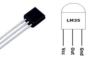
Temperature Sensor LM35:
LM35 is three pin transistor like device. It has VCC, GND and OUTPUT. This sensor provides variable voltage at the output based on temperature. “LM35” provides output in degree Celsius and can sense up to 150 degree Celsius temperature.
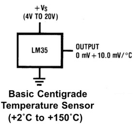
For every +1 centigrade rise in temperature there will be +10mV higher voltage at the output pin. So if the temperature is 0◦ centigrade the output of sensor will be 0V, if the temperature is 10◦ centigrade the output of sensor will be +100mV, if the temperature is 25◦ centigrade the output of sensor will be +250mV.
Setting up Reference Voltage for Op-amp LM358:
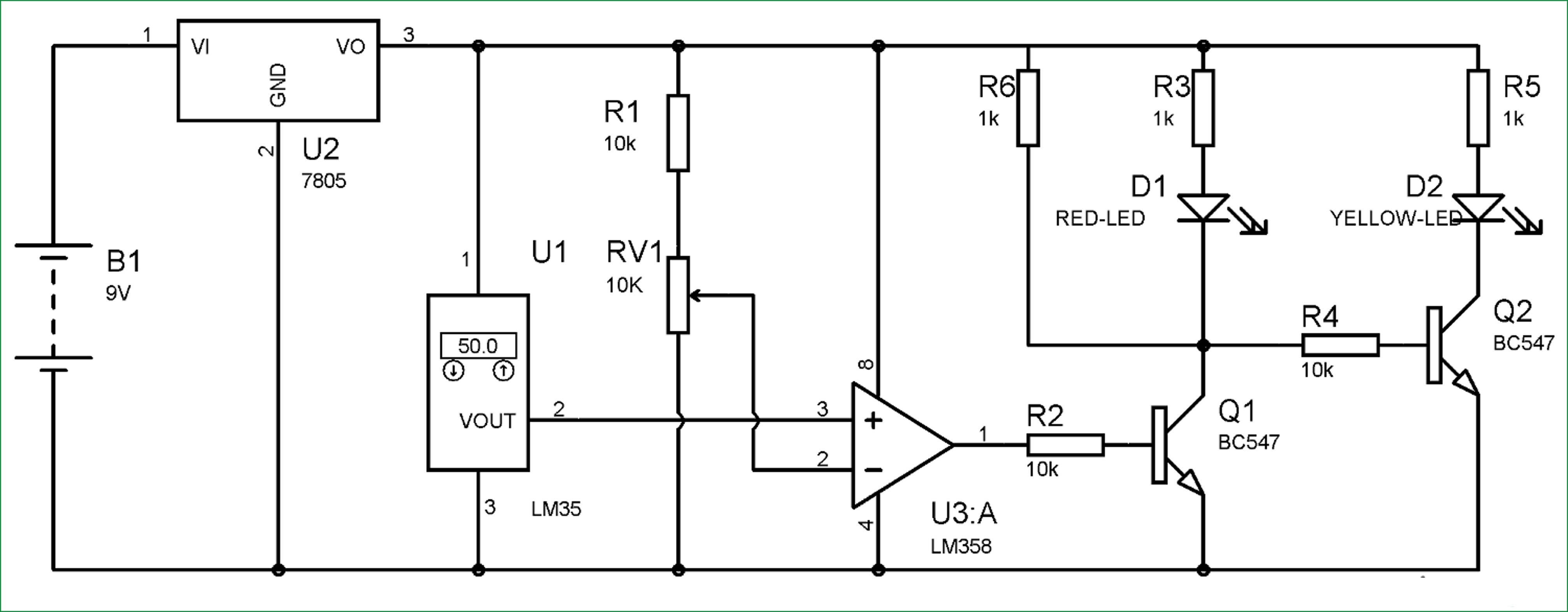
Here we have used Op-amp LM358 to compare the output voltage of LM35 with the reference voltage. As mentioned we have set the circuit for threshold voltage 50 Degree, so to trigger the op-amp at 50 Degree, we need to set the reference voltage to 0.5 volt, as at 50 degree temperature LM35 output voltage will be 0.5 volt or 500mV. Reference voltage is the voltage at Pin no 2 of LM358 (seen circuit diagram below).
Now to set the reference voltage, we have created a Voltage Divider circuit by using resistor R1 and Variable resistor RV1 of 10k. By using the above formulae you can set the reference voltage accordingly and can change the Threshold Temperature. Like to set the 50 degree Celsius temperature as triggering value, you can set the potentiometer roughly at 8k:2k like:
Vout = (R2 / R1 + R2) * Vin
(here R2 is second part of potentiometer:2k ohm and R1 is R1 + first part of potentiometer: 10k+8k)
Vout = (2 / 18 + 2) * 5 = 0.5v
Op-amp LM358:
Op-amps are also known as Voltage Comparators. When voltage at non-inverting input (+) is higher than the voltage at inverting input (-), then the output of comparator is High. And if the voltage of inverting input (-) is Higher than non-inverting end (+), then output is LOW. Know more about working of op-amp here.
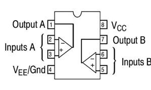
LM358 is a Dual Low Noise Operational Amplifier which has two independent voltage comparators inside. This is a general purpose op amp which can be configured in many modes like comparator, summer, integrator, amplifier, differentiator, inverting mode, non- inverting mode, etc.
Circuit Diagram: