
Fire alarms are prime necessities in modern buildings and architectures, especially in banks, data centers and gas stations. They detects the fire in ambiance at very early stage by sensing smoke or/and heat and raise an alarm which warns people about the fire and furnish sufficient time to take preventive measures. It not only prevents a big losses caused by deadly fire but sometimes proves to be life savers. Here we are building one simple fire alarm system with the help of 555 Timer IC, which will sense the fire (temperature rise in surrounding), and trigger the alarm.
The key component of the circuit is Thermistor, which has been used as fire detector or fire sensor. Thermistor is temperature sensitive resistor, whose resistance changes according to the temperature, its resistance decreases with the increase in temperature and vice versa.
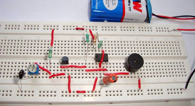
We have built the circuit using, mainly three components that is, Thermistor, NPN transistor and 555 Timer IC. You can find more such simple circuits here in this electronic circuits section.
Working Concept
Here the 555 timer IC has been configured in Astable mode so that Alarm (Buzzer) can produce an oscillating sound. In Astable mode, capacitor C charges though resistance R1 and R2, till 2/3 Vcc and discharges through R2 till it reaches to 1/3Vcc. During the charging time OUT PIN 3 of 555 IC remains HIGH and during discharging it remains LOW, thats how it oscillate. We have connected a Buzzer to OUT pin, so that it produce beep sound, when 555 is high. We can control the oscillation frequency of the alarm by adjusting the value of R2 and/or capacitor C.
Components
555 Timer IC
NPN Transistor BC547
Thermistor (10K)
Resistors (1K, 100K, 4.7K)
Variable resistor (1M)
Capacitor (10uF)
Buzzer and Battery (9v)
Circuit Diagram and Explanation
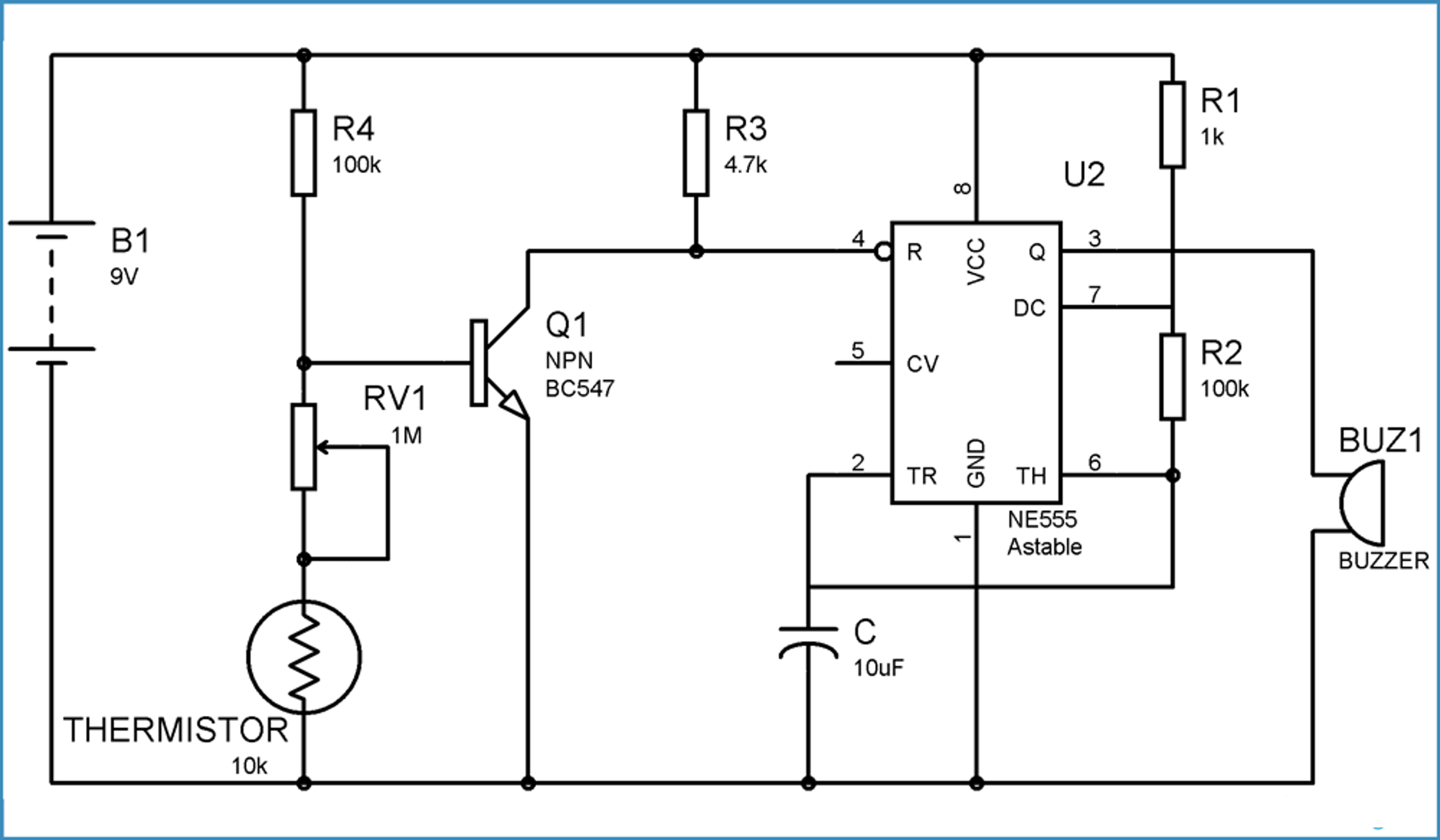
You can see the circuit diagram of fire alarm in above figure. When there is no FIRE, thermistor remains at 10k ohm. And transistor remains at ON state because there is sufficient voltage across the base-emitter of transistor, which makes it ON. When the Transistor is ON, Pin 4 (RESET) is connected to the Ground, and when Reset pin is Grounded, 555 IC doesn’t operate.
Now when we start heating the Thermistor through Fire, its resistance starts to decrease, and when its resistance decreases, the voltage at the base of Transistor starts to decrease and when the voltage becomes less than the operating voltage (base-emitter voltage VBE) of transistor, then transistor becomes OFF. And when transistor becomes OFF, Reset pin of 555 timer IC, gets positive voltage through R3, and 555 IC starts to work and buzzer beeps.
In transistor, usually 0.7v voltage is required across the Base and Emitter, to turn it ON. So we have to carefully adjust the value of Variable resistance RV1 and Thermistor, to make the circuit work properly. To do this remove the thermistor and let RV1 be the grounded, now adjust the value of RV1 to that point, where even slight turning of the RV1 starts the Buzzer. Means from this point, if we decrease the resistance, even very little, Buzzer starts to beep. Now at this point, connect the thermistor again.
We should also note that we can also build a Fire alarm circuit, using DR25 germanium diode, as it works as heat sensor. When DR25 germanium diode is connected in reverse bias, it has a very high reverse resistance and it only conducts at more than 70 degree of room temperature.