
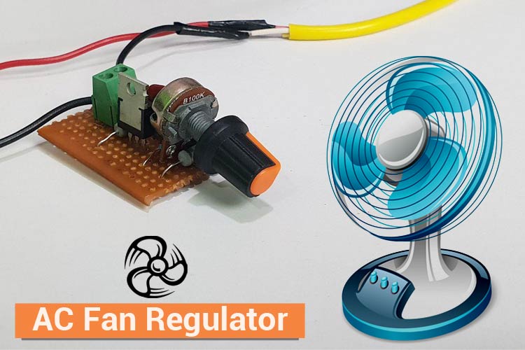
A generic AC fan regulator circuit is essentially used to vary the speed of the fan. In this project, we will build our own fan regulator with minimum components and for better efficiency. Generally, the fan generates a humming noise when brought to use with different fan regulator circuits, our circuit uses DIAC and a TRIAC and produces minimum to no humming noise and works like a charm! We also have designed multiple fan speed control circuits and also implemented IoT techniques to control them, go ahead and take a look at those amazing circuits for reference if you are interested.
Components Required to build an AC Fan Regulator
The components required to build a TRIAC fan regulator circuit are listed below:
- 500k ohm Potentiometer
- BT 136 TRIAC
- DB3 DIAC
- 0.1uf/400v Capacitor
- 10k ohm resistor
- 2 pin Terminal Block
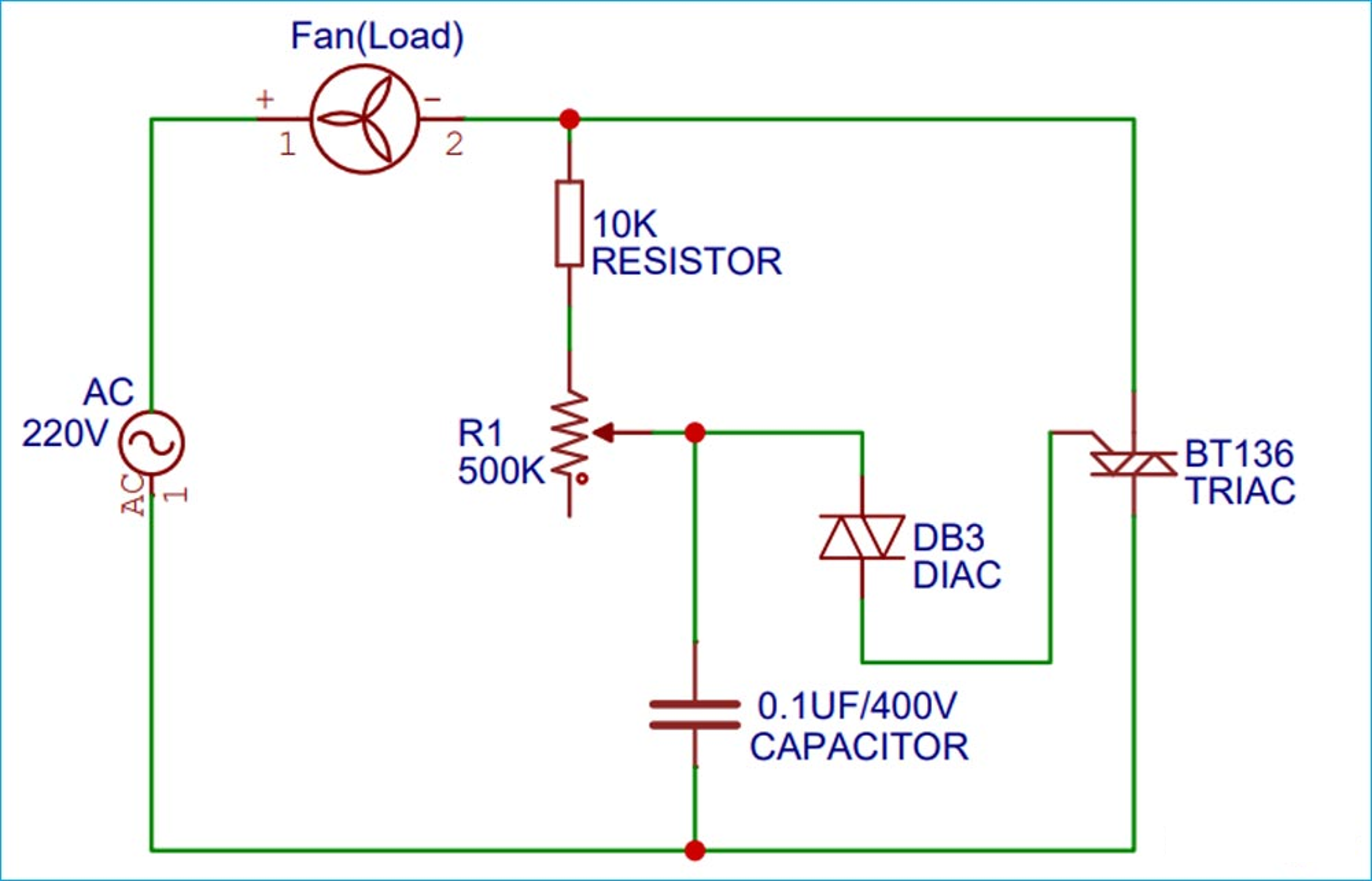
Circuit Diagram for the AC Fan Regulator
The AC fan regulator circuit diagram is given below. The 220V AC mains voltage is given as the input to the one terminal of the fan (load) and the other terminal of the fan is connected to the one leg of the 10K ohm resistor. The 10K ohm resistor will be connected to the one terminal of the 500K ohm potentiometer, whereas the output terminal will be shorted and connected to the one pin of the DIAC and to the 0.1uF capacitor. (DIAC does not have a polarity, so it can be connected from any end). The DIAC’s other end-pin is connected to the Gate terminal of the TRIAC, which basically controls the ON and OFF state of the TRIAC. The 10K ohm resistor is connected to the MT2 pin of the TRIAC. The connection is quite simple and can be made over a perfboard. We can also design our own PCB board to house all the components easily.
Tip:
- Use a heat sink with the TRIAC as it may heat up after some time of its working or with high wattage appliances.
- Load capacity is <200 watts. If you wish to use a higher wattage load, use other variants of BTA TRIACs.
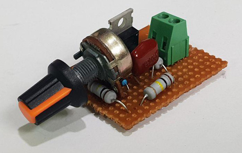
I have built this circuit on a zero PCB for testing it and my board after soldering all the components is looked like as shown in the image below. As you can see, the project looks simple and easy, so I would also recommend you to get your Veroboard and get started with it.
Quick Introduction for TRIAC and DIAC
The two main components used in the circuit are the TRIAC and the DIAC, let us quickly understand the basics of their working. You can also check out the detailed article on the working of TRIAC and the working of DIAC if you wish to explore more.
TRIAC: TRIACs are the components used in controlling the AC signals. They are used in multiple applications where high-power switching is required in AC waveforms. TRIACs are generally used in AC dimmer circuits and come in very handy when trying to control the speed of a fan or as a dimmer to the LED bulb.
DIAC: DIAC stands for Diodes for Alternating Current. It is a bi-directional component having two electrodes. It is another component of the Thyristor family. It only works when it surpasses its breakover voltage (VBO) and is usually used to trigger the TRIACs.