
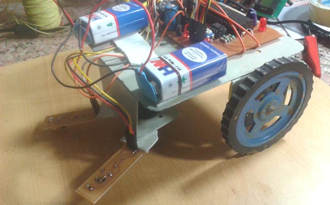
Line follower Robot is a machine which follows a line, it may be a black line or a white line. Basically two types of line follower robots are: one is black line follower which follows black line and second one is white line follower which follows white line. Line follower actually senses the line and run over it. In our previous projects, we have made a black line follower robot using arduino but this time we are going to make white line follower using 8051 microcontroller. In this tutorial, we will also cover how to make a printed circuit board for line follower robot at home in low price.
Concept of Line Follower Robot
Concept of line follower is related to light. We have used the behaviour of light at black and white surface. When light fall on a white surface it will almost full reflects and in case of black surface light is absorbed by black surface. This explained behaviour of light is used in this line follower robot.
In this line follower robot project we have used IR Transmitters and IR receivers also called photo diodes for sending and receiving light. IR transmits infrared lights. When infrared rays falls on white surface, it is reflected back and catched by photodiode and generates some voltage changes. When IR light falls on black surface light is absorbed by the black surface and not rays reflect back, so photo diode did not received any light or rays. Here in this line follower robot when sensor senses white surface then microcontroller gets 0 as input and when senses black line microcontroller gets 1 as input.
Circuit Explanation
We can divide the whole line follower robot into various sections like sensor section, control section and driver section.
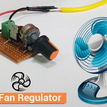
Sensor section: This section contains IR diodes, potentiometer, Comparator (Op-Amp) and LED’s. Potentiometer is used for setting reference voltage at comparator’s one terminal and IR sensors sense the line and provide a change in voltage at comparator’s second terminal. Then comparator compares both voltages and generates a digital signal at output. Here in this circuit we used two comparator for two sensors. LM358 is used as comparator. LM358 has inbuilt two low noise Op-amp.
Control Section: 8051 microcontroller is used for controlling whole the process of line follower robot. The outputs of comparators are connected to pin number P0.0 and P0.1 of 8051. 8051 reads these signals and send commands to driver circuit to drive line follower.
Driver section: Driver section consists motor driver and two DC motors. Motor driver is used for driving motors because microcontroller does not supply enough voltage and current to motor. So we added a motor driver circuit to get enough voltage and current for motor. Microcontroller sends commands to this motor driver and then it drive motors.
Working of Line Follower Robot using 8051
Line follower robot senses white line by using sensor and then sends signals to microcontroller. Then microcontroller drives the motor according to sensors’ output.
Here in this project we are using two IR sensors pair. Suppose we are calling left sensor and right sensor of IR sensor Pair, then both left and right sensors sense nothing or black line then robot move forward.
And when left sensor senses white line then robot turn left side.
and when left sensor sense white line then robot turns to right side until both sensor comes at black line or senses nothing surface.
And when both sensors comes on white line, robot stop.
8051 Based Line Follower Robot Circuit
Circuit is very simple for this line follower robot. Output of comparators is directly connected to pin number P0.0 and P0.1 of microcontroller. And motor driver’s input pin 2, 7, 10 and 15 is connected at pin number P2.3, P2.2, P2.1 and P2.4 respectively. And one motor is connected at output pin of motor driver 3 and 6 and another motor is connected at 11 and 14.
Programming Explanation
In program first of all we defines input and output pin. And then in main function we checks inputs and sends output according to inputs to output pin for driving motor. For checking input pin we used “if” statements.
There are four conditions in this line follower. We have used two sensor namely left sensor and right sensor.
Input | Output | Movement of Robot | ||||
Left Sensor | Right Sensor | Left Motor | Right Motor | |||
LS | RS | LM1 | LM2 | RM1 | RM2 | |
0 | 0 | 1 | 0 | 1 | 0 | Forward |
0 | 1 | 1 | 0 | 0 | 0 | Turn Right |
1 | 0 | 0 | 0 | 1 | 0 | Turn Left |
1 | 1 | 0 | 0 | 0 | 0 | Stop |
We have writen the program according to above table conditions. See the complete code of this 8051 based line follower robot at the bottom of this page to understand the concept.
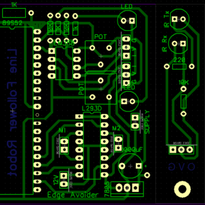
PCB Layout
Here is the PCB layout for line follower robot
Code
// C Program for line follower robot using 8051 microcontroller
#include<reg51.h>
sbit ls=P0^0;
sbit rs=P0^1;
#define motor P2
#define forward 0x06
#define turn_left 0x82
#define turn_right 0x14
#define stop 0x00
void main()
{
motor=stop;
while(1)
{
if(ls && rs)
motor=forward;
else if(!ls && rs)
motor=turn_left;
else if(ls && !rs)
motor=turn_right;
else
motor=stop;
}
}
#HAPPY BUILDING #EDUTECH4.0